Multi-mine
Highlights
Managing multiple pits together optimizes the entire project’s schedule and value. MiningMath’s global optimizer analyzes all mines simultaneously for integrated results.
- Enables integrated optimization across pits, avoiding siloed scheduling and manual rework, unique in modeling interdependencies.
- Supports fast scenario iteration via API scripting, lowering turnaround time compared to manual approaches.
- Its globally optimal algorithm, validated academically and in operation, maximizes combined mine profitability.
MiningMath’s global optimization algorithm effectively addresses the challenges of integrated multi-mine projects by considering all pits simultaneously. Unlike individual pit optimization, this approach delivers a comprehensive solution that optimizes the entire project, providing a more cohesive and strategic overview.
Not using MiningMath?
Multi-mine projects often hold hidden opportunities for maximizing value. Given their inherent complexity, it’s common to apply simplifications that, while convenient, can lead to sub-optimal solutions when using traditional LG/Pseudoflow methodologies instead of MiningMath. These simplifications may ultimately reduce the project’s potential value from a mathematical standpoint.
Formatting the block model
For multi-mine projects, the block model must include all mining regions for simultaneous optimization. If your pits are mapped in separate datasets, it’s essential to follow the steps outlined below:
Work with a single block model or single pit first, run the initial tests and understand this region before handling the block model modification.
Try to eliminate meaningless blocks, which would not affect the solution and could increase complexity.
Add a second model or pit to explore the process of working with multi-mine projects. This combined block model file should meet the same requirements as a single model, as outlined on the data formatting page, ensuring unified characteristics.
Experiment with surface adjustments to refine results, filter out regions you don’t wish to mine, and apply other guidance as needed. Since MiningMath surface files maintain a consistent order, using an Excel file (available here) can be a helpful tool for these modifications.
Use mining fronts if you’d like to control the material extracted from each region.
Add the other regions and start using everything that you wish.
Using Real-World UTM Coordinates
When using actual UTM coordinates from mines that are geographically far apart, the combined block model spans a massive area with large empty zones between deposits. This leads to:
- Significantly slower performance
- Higher memory usage
- Potential optimization failures
Simplifying with a Local Coordinate System
Instead of directly using UTM, introduce a simplified, local coordinate system:
- Choose an arbitrary origin (e.g., 0, 0, 0) close to all deposits
- Shift (translate) each mine’s coordinates by a constant offset so they all align near the origin
- This repositions models close together, eliminating wasted space
How to Translate Coordinates
- Add (or subtract) a fixed value to X and Y so the mine is moved into the new system
- Z coordinate can typically stay the same if elevation ranges are similar between mines
- Mine A original UTM centre: (600 000, 4 500 000)
- Mine B original UTM centre: (601 000, 4 501 500)
- Define origin = (600 000, 4 500 000)
- Translation offsets: A = (0, 0), B = (–1 000, –1 500)
- New local coordinates: A ≈ (0, 0), B ≈ (0, 0)
Ensure Non‑Overlap & Model Integrity
After translation and integration:
- Check that different mine models do not overlap spatially
- Confirm there are no conflicts in block assignments
- Validate all geometric rules (e.g. mining fronts, pit shapes) still make sense
Geometric constraints
The current version of MiningMath applies the same values for vertical rate, bottom width, and mining width across the entire block model. However, in a multi-pit scenario, each pit may have unique geometric parameters that impact selectivity. In these cases, we recommend setting the parameters for one pit, fixing its solutions (as the force and restrict mining settings have the highest priority), and then starting the optimization of the other pits. This approach ensures that the optimization considers the mass already planned for extraction from the first pit.
Example workflow
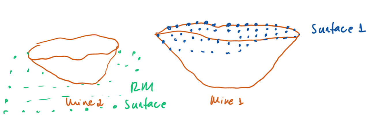
An efficient workflow starts by running an initial scenario without geometric parameters to serve as a validation or best-case scenario for scheduling optimization. Next, configure a scenario using the geometric parameters of the most selective mine—meaning the smallest widths and highest vertical rate (VR)—to create the least constrained scenario in terms of geometry. The surfaces generated from this setup can then be used to fix solutions for Mine 1.

For example, you could take Surface 1 and adjust the elevation in other areas to reflect the mass extracted in Period 1 from Mine 1, as well as the potential extraction from the second pit. With these results, you can refine surfaces or mining fronts, conduct a sensitivity analysis of the geometric parameters across multiple projects, and still maintain the benefits of global optimization.